

1S 3.7v BMS 3A FOR 18650 LITHIUM
Share :
The 3.7V 3A 18650 BMS is a small, essential circuit board designed to protect a single Li-ion battery cell (1S), such as an 18650, from being damaged during charging and discharging.
Here is a breakdown of its function, specifications, and how it works:
The module acts as a Battery Management System (BMS) or Protection Circuit Module (PCM) for a single cell.
| Specification | Value | Function/Meaning |
| Nominal Voltage | 3.7V | The standard operating voltage for a Li-ion cell (like the 18650). |
| Series Configuration | 1S | Means it is for a Single Cell (1 cell in Series). |
| Max Continuous Current | 3A | The maximum current the board is designed to safely handle for both charging and discharging. |
| Charging Voltage | 4.2V | The required voltage input to charge the cell through the BMS. |
| Overcharge Protection | approx 4.25V | Cuts off the charger when the cell voltage hits this level to prevent damage/fire. |
| Over-Discharge Protection | approx 2.5V | Cuts off the load when the cell voltage drops to this level to prevent irreversible damage. |
| Protection Type | Overcharge, Over-discharge, Short Circuit, Overcurrent. | Essential safety features for extending the battery's lifespan and ensuring safe use. |
This type of low-current, single-cell BMS is typically used in:
Small DIY power banks (when combined with a charging module like TP4056).
Low-power electronic projects (e.g., Arduino or Raspberry Pi Zero projects) where the total current draw is under A.
Single-cell rechargeable devices like small flashlights or personal electronic gadgets.
Limitations
This module is not suitable for high-current applications. You cannot use this 3A module for:
High-power motors (like most drills or vacuum cleaners).
High-draw LED lights (e.g., high-wattage COB LEDs).
Any application that demands a continuous current of more than 3A.
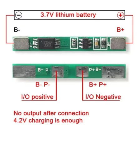
The module typically has four main solder points:
| Pin Label | Connection Point | Purpose |
| B+ | Battery Positive | Connects to the positive terminal of the 18650 cells. |
| B- | Battery Negative | Connects to the negative terminal of the 18650 cells. |
| P+ | Charge/Load Positive | Output point for the load, and Input point for the charger's positive wire. |
| P- | Charge/Load Negative | Output point for the load, and Input point for the charger's negative wire. |
The BMS is wired directly to the battery terminals, and all charging current and load current must pass through the P+ and P- terminals to ensure the protection circuit is active.