

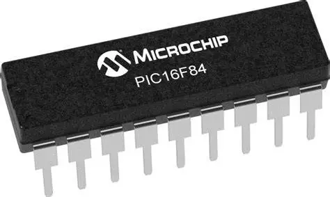
PIC16F84 8BIT MICROCONTROLLER
PIC16F84 8BIT MICROCONTROLLER
NGN2,000.00 NGN2,200.00
Share :
Product Details
The PIC16F84A (an enhanced version of the original PIC16F84) is an 8-bit microcontroller from Microchip Technology's popular mid-range family. It's historically significant and often used as a starting point for learning PIC programming due to its simple instruction set and feature set.
Key Features of the PIC16F84A
The PIC16F84A operates on a RISC (Reduced Instruction Set Computer) architecture, featuring:
| Feature | Specification | Notes |
| Architecture | 8-bit RISC CPU | Simple instruction set with only 35 single-word instructions. |
| Instruction Cycle | 200 ns at 20MHz | All instructions are single-cycle except for program branches. |
| Program Memory | 1K words (1024 times 14-bit words) Flash | Reprogrammable Flash memory for code storage. |
| Data Memory | 68 Bytes RAM, 64 Bytes EEPROM | EEPROM provides non-volatile storage for permanent data. |
| Max Speed | 20MHz | External oscillator is required (crystal or RC circuit). |
| I/O Pins | 13 bidirectional pins | Grouped into two ports: PORTA (5 pins) and PORTB (8 pins). |
| Peripherals | 1 8-bit Timer/Counter TMR0 | Includes an 8-bit programmable prescaler. |
| Special Features | In-Circuit Serial Programming ICSP | Allows programming without removing the chip from the circuit. |
| Power Features | Watchdog Timer WDT, Power-on Reset POR, Power-up Timer PWRT | Used for system reliability and power management. |
| Operating Voltage | 2.0V to 5.5V | Wide operating voltage range. |
Pin Configuration (18-Pin PDIP)
The PIC16F84A is commonly found in an 18-pin DIP package. Its 13 I/O pins are highly configurable, with some pins having multiplexed functions:
| Pin No. | Name | Primary Function | Alternate Functions |
| 1 | RA2 | PORTA I/O Pin 2 | |
| 2 | RA3 | PORTA I/O Pin 3 | |
| 3 | RA4/T0CKI | PORTA I/O Pin 4 | T0CKI (Timer0 Clock Input) |
| 4 | MCLR / V_PP | Master Clear (Reset) | Programming Voltage Input |
| 5 | V_SS | Ground 0V | |
| 6 | RB0/INT | PORTB I/O Pin 0 | INT (External Interrupt) |
| 7-11 | RB1 to RB5 | PORTB I/O Pins 1-5 | RB4 to RB7 support Interrupt-on-Change |
| 12 | RB6 | PORTB I/O Pin 6 | ICSP Clock |
| 13 | RB7 | PORTB I/O Pin 7 | ICSP Data |
| 14 | V_DD | Positive Power Supply | |
| 15 | OSC2/CLKOUT | Oscillator Output | |
| 16 | OSC1/CLKIN | Oscillator Input | External Clock Source Input |
| 17 | RA0 | PORTA I/O Pin 0 | |
| 18 | RA1 | PORTA I/O Pin 1 |
Note on I/O: Each of the 13 I/O pins can be configured individually as either a digital input or a digital output using the TRIS registers (TRISA and TRISB). They can also sink or source a maximum current of about 25mA per pin.
Ratings And Reviews