

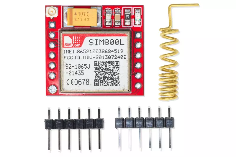
SIM800L GSM/GPRS 2G MODULE
Share :
The SIM800L is a compact and cost-effective GSM/GPRS module that allows microcontrollers (like Arduino) to connect to a 2G cellular network for voice, SMS, and data communication.
Key Features and Specifications
| Feature | Description |
| Network Type | Quad-band 850/900/1800/1900MHz (2G GSM/GPRS). |
| Communication | Sends/receives SMS, makes/receives Voice\ Calls, and supports GPRS (data) for internet communication. |
| Control | Controlled using standard AT\ (Attention)commands sent via its serial UART interface. |
| Operating Voltage | 3.7V to 4.2V DC. Crucially, it requires a robust power supply capable of providing up to 2A peak current during transmission bursts (a common point of failure for beginners). |
| Logic Voltage | 2.8V logic level for its UART (RX/TX) pins. Using 5V logic (from an Arduino Uno) requires a logic level converter to prevent damage. |
| Antenna | Typically uses a small PCB antenna or a 3dB external antenna connected via a U.FL connector. |
| SIM Card | Requires a 2textG-compatible\ \Micro-SIM card. |
| Power Consumption | Extremely low in Sleep mode (approx 0.7mA), but has high current spikes (approx 2A) during active communication. |
Essential Module Components
The SIM800L module typically includes:
SIM800L Chip: The main cellular processor.
SIM Card Holder: Slot for inserting the Micro-SIM card.
Antenna Connector: U.FL connector for the external antenna.
LED Indicator: A net light indicator that shows the network status:
Slow Blinking (approx once every 3 seconds): Connected to the network and ready for commands.
Fast Blinking (approx once per second): Searching for a network.
Very Fast Blinking (approx once every 800 ms): Data transmission in progress (GPRS mode).
Breakout Pins: Pins for power (VCC/GND), UART communication (TX/RX), and sometimes a reset pin.
Interfacing and Use
To use the SIM800L with a microcontroller:
Power: Provide the required approx 4V with a dedicated power source (not usually the microcontroller's 5V or 3.3V supply) capable of the high current draw.
Serial Communication: Connect the module's TX and RX pins to the microcontroller's RX and TX pins, ensuring a 2.8Vlogic\ level translation if the microcontroller uses 5V.
Control: Send AT commands (e.g.,
AT+CMGF=1to set SMS text mode,AT+CMGS="123456789"to send a message) to control its functions.