

SLA-12VDC-SL-A 12VDC RELAY (USED)
Share :
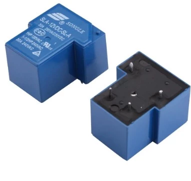
The SLA-12VDC-SL-A is a high-power, PCB-mount T90-style relay. It is one of the most common "workhorse" relays used in power electronics, specifically designed to handle high-current loads in a compact footprint.
SLA: The series designation (typically 30A capacity).
12VDC: The nominal coil voltage required to activate the relay.
SL: Indicates the "Sealed" construction type (protected against dust and moisture).
A: Contact Form — SPST-NO (Single Pole Single Throw, Normally Open). This version has 4 pins total (2 for the coil, 2 for the switch).
This relay is favored because it can handle significant AC power while being triggered by a standard 12V DC signal.
| Feature | Specification |
| Contact Rating | 30A at 250VAC / 30VDC |
| Max Switching Power | 7,200 VA / 900 W |
| Coil Power | Approx. 0.93W |
| Contact Material | Silver Alloy (AgSnO_2) for arc resistance |
| Dielectric Strength | 2,500VAC (between coil and contacts) |
In the context of the high-power projects, we have discussed (like the EE42 500W Inverter or the EE55 30A Charger), the SLA relay serves as a critical protection and control component:
Because it is rated for 30A, it can safely handle the full output of a 3000W inverter. You can use it to "gate" the power, ensuring the AC outlet only becomes live once the EGS002 control board confirms the voltage is stable.
In your 30A Flyback Charger project, the "A" (Normally Open) version of this relay is ideal. It ensures the battery is physically disconnected from the charging circuit unless the charger is powered on and healthy, preventing the battery from "back-feeding" into the circuit.
In large inverters, this relay is often used to short-circuit the "Pre-charge resistor" once the high-voltage capacitors have reached their target voltage.
Pin Configuration: The T90/SLA footprint is unique. The coil pins are standard 2.54mm spacing, but the power pins are much thicker and wider to handle the 30A load.
Heat & Solder: When soldering this to a PCB for a 30A load, a standard solder joint is not enough. You must ensure a "high-fillet" solder joint and, ideally, reinforce the PCB traces with copper bus wire or a thick solder bridge to prevent the board from acting like a fuse.
The "SL" Advantage: Since yours is the "SL" (Sealed) version, it is safe to use in environments with high humidity or dust, which is common for solar inverters mounted in garages or outdoor enclosures.